5
5
 0
0
In this post I will document what I have done to configure a DUET3D 3 to work with a KillerBee (a workbee updated with the excellent Ratrig update). While this is a killerbee the process is not specific to that and any similar CNC machine will work in the same manner
In this article I will cover
- The board itself
- Motor connections
- Endstops
- Fans
- PanelDue touchscreen
- Laser
- Spindle with VFD
- Z probe (switch type as supplied by ooznest etc)

The above image is that of the unboxed card, nothing much to see here but some important points to note, no wifi, no usb setup needed.
So the first part of the process is to prepare the SD card. one comes with the DUET and this is a dual format card. Initially I am going to be using the machine in stand alone format and so I will start with that (this means no single board computer like a pi directly attached).
You need to setup the card, some things are on there but not really much, so take the sys and macros directories from your old machine and copy then straight into here. (this assumes your old machine is the same size as the machine this board is going onto).
If you are moving from a wi-fi board, or you want to change your machines IP settings you will need to edit the config.g file you copied across, you must switch on ethernet within the file to get the board to work in stand alone mode.
You then need some firmware files, nice and easy here you get them from the DUET website Releases · Duet3D/RepRapFirmware (github.com) as of now I used

I am not sure that I needed both of these but better safe than sorry. I syspect that just the zip file was needed.
NOTE: During the setup version 3.3 was released and this is needed if you want Z probe features
I want the CNC UI and so I have also added another file, you get this from Releases · Duet3D/DWC-CNC (github.com) and it’s important that you use a version of firmware that this is compatible with.
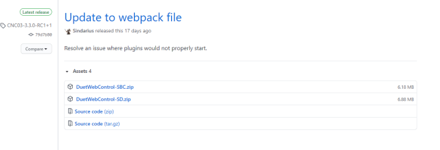
Use the SD zip file for stand alone machines, we would have used the SBC one instead had we been setting the board up with a pi attached.
so when you have done that take the SD card from your machine and put it into the DUET.
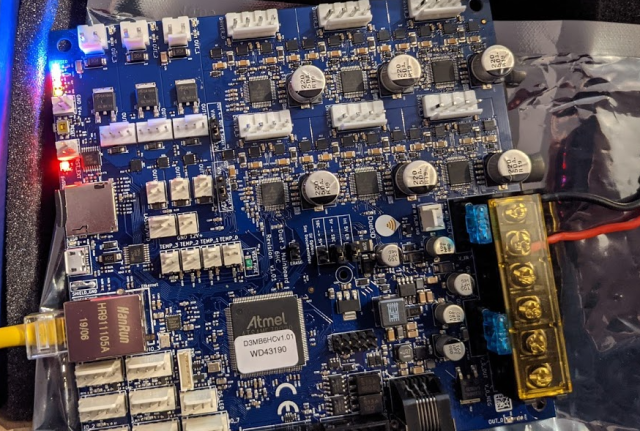
Power cables are now needed, the board if labelled – and + but it’s not the largest of text so the above image may help more.
Then you plug in your ethernet cable, and then switch on the machine.
If all works well the a set of LED’s in the top left come on, a red one below it blinks and you should see a green flash at the network port.
You should now have web access to the board

In my case I left the board set to use DHCP so I needed to find the address.
and you can check the firmware version

The next main task is to move all the other wires from the DUET 2 to the DUET 3. Logically this should be simple since we will be mostly moving like to like but the new board has it’s cables much more segregated so we need the wiring guides.
The DUET 2 board layout is document here Duet Wiring Diagrams – Duet3D (dozuki.com)
We can start with the motor wiring so this section of the diagram is handy
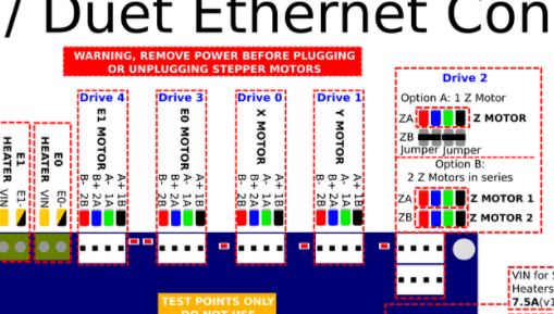
we see that they are labelled drive 1 thru 4 but not in order
The board layout for the 3 is here Duet 3 Mainboard 6HC Wiring Diagram – Duet3D (dozuki.com)

so we want to copy drive 1 to drive 1 etc however what is really annoying is that the connectors have changed from the MOLEX KK on the DUET 2 so once you get to this point you are heading to a point of no return
It is important to note what colour of wire you have and make sure that you keep it to the same order as the colours in the board diagrams
For info the DUET 2 colour codes are as follows and the DUET 3 ones are below that
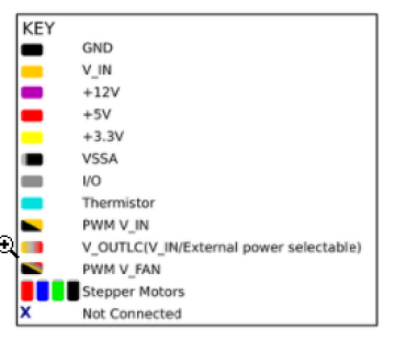
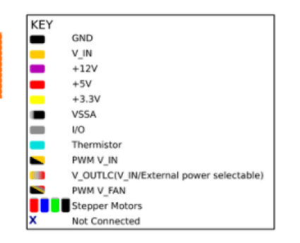
Luckily these all consistent which makes the job a lot easier.
so some new connectors later and I’m starting to rewire my motors, I decided to also move to 4 core screened cable at this point since I will be getting a spindle soon.
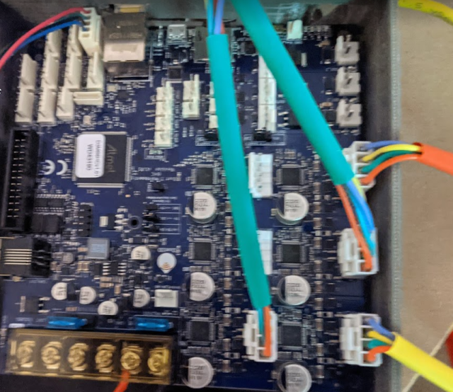
so I have opted to wire up some 20AWG silicone wite to the duet connectors (JST VH) and have a pluggable 4 block connector to connect these to the motor wires. I made it pluggable (the terminal blocks pull apart in the middle so I can switch cables easier in the future. I ordered a small reel of cable from CPC at the same time a new PI4 for when I switch the DUET to SBC mode. In the above image green sheaf is the Y motors, red is X and yellow is Z
I did not want to alter my old motor cables at this point so I created new cables that connected to the JST SM ends of my motors. Once I am happy everthing is working I will be able to just pull out my old motor cables and perhaps use them for another project
ENDSTOPS
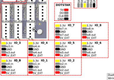
Endstops have also changed plug type and now we use 3 of the 9 available IO ports for this. the image belows shows one test wired, we use two pins of the five, the grnd pin and the in pin (we could use the out pin I suspect as well), in the orientation shown in the image these are the 3rd and 2nd righmost pins. These simply attach to your existing 2 wire limit switches. In the image below from top to bottom are X, Y and Z switches.
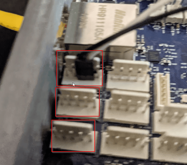
The config.g file needs to be changed to work with the new port but this is rather easy
; Configure Endstops
M574 X2 S1 P"io0.in"  ;configure active-low endstop for low end on X via pin io0.in
M574 Y2 S1 P"io1.in"  ;configure active-low endstop for low end on Y via pin io1.in
M574 Z2 S1 P"io2.in"  ;configure active-low endstop for low end on Z via pin io2.in
;M574 X2 Y2 Z2 S0 ; ORIGINAL WORKBEE LINE FOR MY MACHINE Set active low endstops

;NOTE if you have a paneldue then X will need changed to a different io port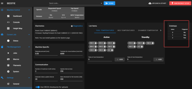
And in the UI showb above you can test the switches, note that 1 and 2 are shown as yes above since I have not wired them up yet but the 0 (x) switch was testing fine for me as a test.
PROXIMITY SENSORS
I plan to switch my machine to use proximity sensors instead of the limit switches, these are obtained fairly easily and the cheapest is probably 3 pin ones that working in the 10-30v range.
These sensors will have 3 wires, brown is the Voltage in wire, blue will be the GND one and the black wire will be the signal wire.
Since we want to use the duets IO pins we need to test that the sensors will actually operator at 5v even with the listed range being 10v min, you can do this by temporarily wiring up the sensor to an IO port and seeing if he sensor lights up when you put it near a metal object. The ones I bought seem to work fine for me https://www.amazon.co.uk/gp/product/B08L3CF7NW
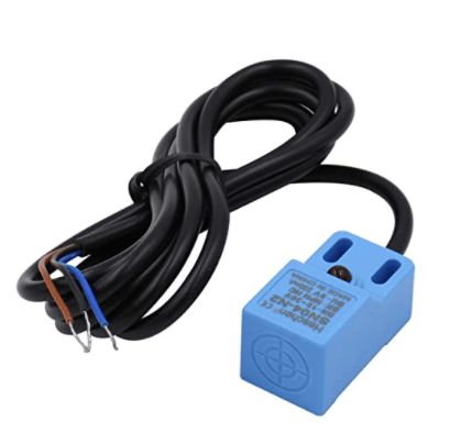
So assuming you get them working you wire black to the .in pin, blue to the GND and brown to the V5_ext. It should them work as a direct replacement for the limit switch
Be aware that you can get different sensing distances, the ones I am trying are set to approx 5mm. if your limit switches and the proximity sensors do not have the same settings for NC or NO you will need to set this in the config.g
FANS
I had a couple of fans from my old duet2 setup so I wanted these set but did not want to use one of the ports I have a use for so OUT7 seemed to be a good place (OUT9 is always on by default but I am using that for spindle control)
M950 F0 C"out7" Q500 ; create fan 0 on pin out7 and set its frequency
M106 P0 S1 H-1 ; set fan 0 value. Thermostatic control is turned off
The above lines in config.g setup a fan linked to out7 and then switch it on
PANELDUE

The Paneldue can only connect to the board using the 4 pin connector and it must be rewired as a 5 pin as per the above image (taken from the duet website). It should also be noted that only the IO-0 port will support the paneldue so I will need to remap my X endstop to another port.
To rewire it easily if you have a terminal remover (or a pin) you can lightly press down on the old connectors, pull them out and the use them again in the new connector. You should slightly bend back up the retaining tab using a fingernail so that it clips in solidly. WARNING the 4 pin wire that came with my machine was the exact wrong way round from the image shown above at the panel end.
OPTLASER
Initial test wiring for optlaser is as follows, using the Out, 3.3V and GND pins from IO7 port
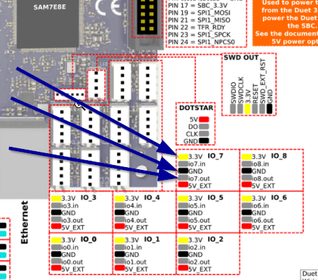
IO7 has been chosen since it is a PWM port, unlike for example IO8 which only allows on and off.
So using the ‘io7.out’ port we need to activate it to use it. This takes two parts, the first is to assign one of the 10 GPIO logical pins to the real pin.
The DUET 3 has the following physical pin names
out0, bedheat
out1
out2
out3
out4
out5
out6
out7
out8
out9,laser,vfd
out4.tach
out5.tach
out6.tach
io0.in
io1.in
io2.in
io3.in
io4.in
io5.in
io6.in
io7.in
io8.in
io0.out
io1.out
io2.out
io3.out
io4.out
io5.out
io6.out
io7.out
io8.out
servo, out10 (only on v0.5, not on v0.6)
pson
spi.cs0
spi.cs1
spi.cs2
spi.cs3
temp0
temp1
temp2
temp3
mcu-temp
so to connect one of these to the logical pin we can use the following gcode, note that we prefix the pin by a !, this means we want to invert it, this for the optlaser gives us 0 being off and 1 being 100%, without the ! the optlaser is the other way round.
M950 P0 C"!io7.out"The above assigns the PHYSICAL laser pin to the VIRTUAL GPIO pin 0 (valid values are 0-9)
M42 P0 S0 ;set laser off initially S1 = 100% 0.5 = 50%I initially started by using the laser pin, but that seems to default to being on which is not great safety wise for a laser and by using 3 pins on IO7 we can make up a molex KK plug for the laser.
For future reference the capabilities of the IO port are as follows
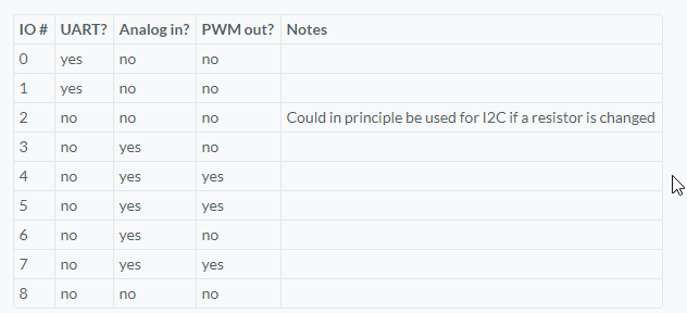
so you can see that 4, 5 and 7 will do for the laser, the others are fine for endstops and relays.
UPDATE: I had some issues using my previous lightburn settings so I revised this. I based the profile now on Marlin and not GRBL since this gives a new option in the lightburn machine settings
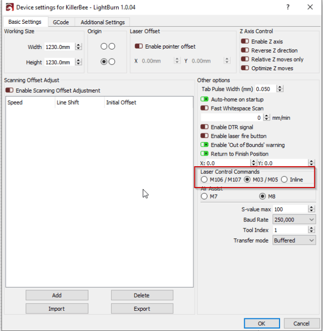
This means that M03 P1 S100 will be created to fire the laser and this will be done before any moves that need the laser are triggered (G1/2/3) and M05 P1 will be created before any G0 moves which are the ones where we do not want the laser to fire during the move.
The full start/end gcode for lightburn under my configuration (laser as T2/P1)
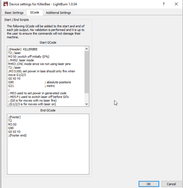
SPINDLE
As part of my upgrades I moved to use a spindle and an invertek VFD, this is still a work in progess
;Spindle

M453 C"!vfd" R24000 Q1000 	;CNC mode, max rpm 24000
M950 R0 C"!vfd" L24000 ; Create spindle index 0
M563 P1 S"Spindle 1" R0 ; Create tool 1 with spindle 0 and call it "Spindle 1"
T1 ; select tool 1
M3 S0
M5					;stop spindle
The above was added to the end of my config.g file and allows me to use M3 and M5 commands to control the spindle motor. I am only getting 75% of the speed asked for at the moment but that may be the convertor.
Anyway to wire this up I bought one of these to give me a conversion from PWM to Voltage for the VFD control https://www.amazon.co.uk/gp/product/B0789738RC
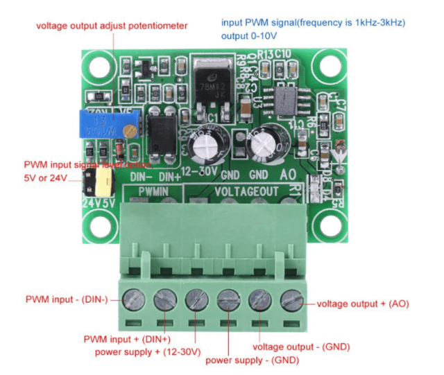
So I wired this using the 2 and 3 pin blocks on the duet for laser/vfd and the voltage out ports go to the VFD

This image was taken from the supplier I used Wiring Diagrams (AiO) + VFD Setup – CNC Routers | 3DTEK
Z Probe
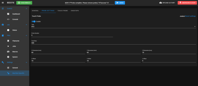
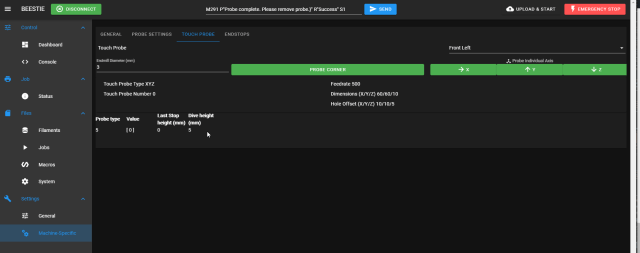
The Z probe was strangely enough the most complex thing to implement with the new board. When you update the firmware, now I am using 3.3.0 there are a lot of changes needed. Firstly you switch the CNC version of the UI Duet3D/DWC-CNC (github.com) and then one of the things missing is a CNC probe function. This version of the firmware however allows plugins to be added so I have written a CNC probe plugin that I can use.
In my case I have a two wire XYZ probe from ooznest, I wire this up just like I did with the endstops and I am using the out4 socket for the probe. so config.g has to change
;out4 as XYZ probe
M558 P5  F500 C"!io4.in"   ; Set probe type 5, Speed 500mm/s and use IO4.in inverted
So a nice simple change here, probes have types now (type 5 is a simple switch) and you can set multiple probes up, in this case probe 0 will be set since I don’t specify a value.
I then add in my plugin to do the probe code and all should be well (I will package up the probe code so anyone can use it)
Multiple Tool settings
ok so now that I have my laser and spindle working I realise that there are issues with products like lightburn and I need to reconfigure it. Since Ideally I want both devices to work with things like the M3 command the solution to that is to define them (reprap 3.3 and above) as tools.
;Spindle

M453    ;params now in M950 for reprap3.3
M950 R0 C"!vfd" L24000 ; Create spindle index 0, with PWM pin on heater 3 and 12000 RPM achieved at full PWM
M563 P1 S"Spindle" R0 ; Create tool 1 with spindle 0 and call it "Spindle"
T1 ; select tool 1
M3 S0
M5					;stop spindle

;laser (as tool 2, spindle 1)
M950 R1 C"!io7.out" L100   ; R=Spindle number, L = max rpm
M563 P2 S"Optlaser" R1 ; Create tool 2(p) with spindle 1(r) and call it "laser"
so in the above T1 will select the spindle for M3 commands, and T2 will switch that to use the laser for the same M3 command. It is worth noting thate M453 (switch to CNC mode) is still needed for BOTH but that this command no longer has tool parameters to it and these are now in M950 commands
Copies of all config files are available here https://dev.azure.com/galcompnet/_git/Killerbee%20Duet%20Config